Grounding Methods
The requirements for grounding of services are found in NEC Sections 250.24(A) and (B). Methods of grounding an electric service are covered in NEC Sections 250.50 and 250.52. In general, all of the following electrodes (if available) must be bonded together to form the grounding electrode system.
- An underground water pipe in direct contact with the earth for no less than 10′
- The metal frame of a building where effectively grounded (columns are tied to rebar down in the footings)
- An electrode encased by at least 2″ of concrete, located within and near the bottom of a concrete foundation or footing that is in direct contact with the earth.
- A ground ring encircling the building or structure, in direct contact with the earth at a depth not less than 2.5′ below grade
- Rod, pipe, or plate electrodes
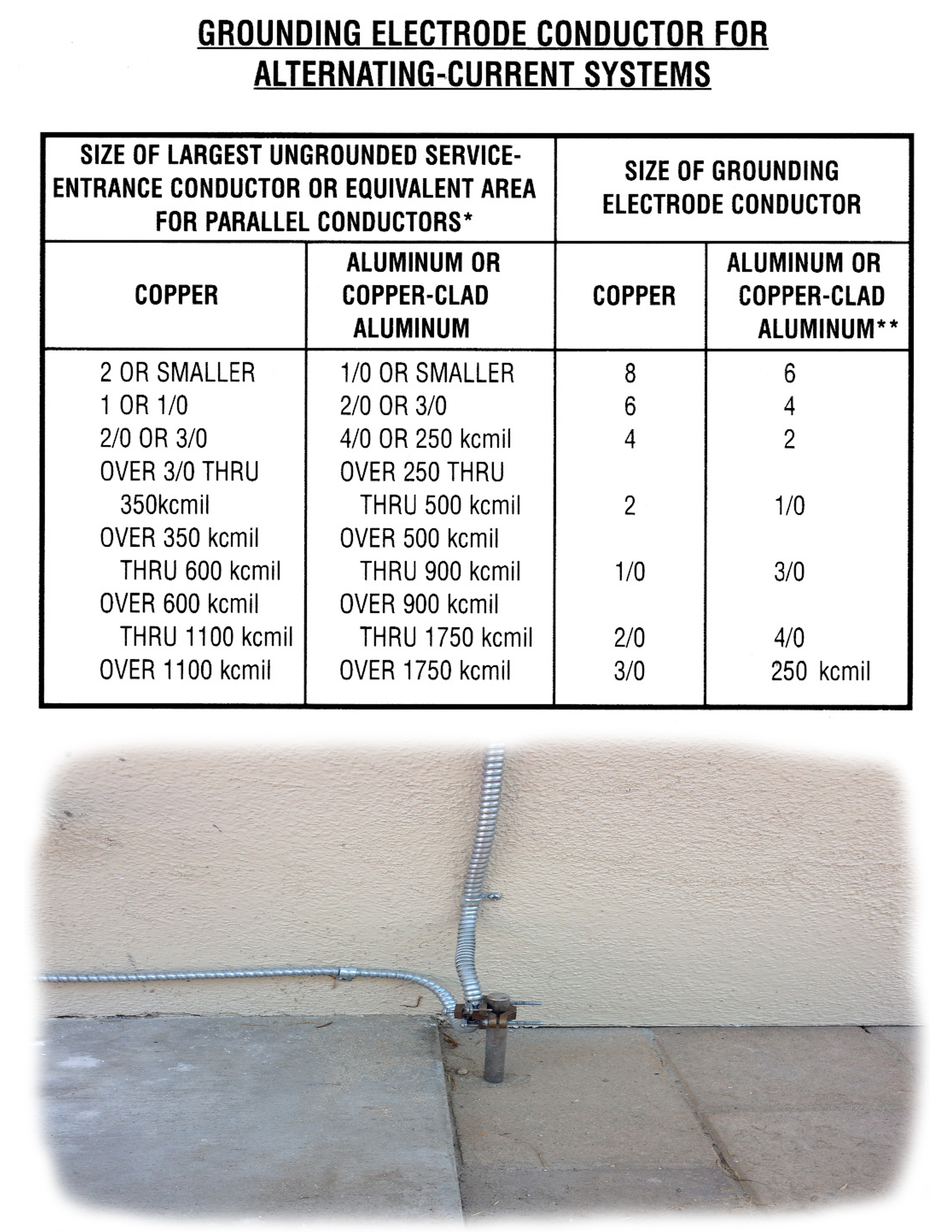
Service Entrance Grounding Conductor
Observing proper grounding and bonding processes and employing reliable materials are essential considerations that contribute to the safety of personnel and equipment over the lifetime of an electrical system. Make sure to hire your Orange County Electrician to install your grounding system.
Properly following the general requirements for grounding and bonding articulated in Section 250.4 (A) of the National Electric Code (NEC) can prevent injuries by limiting the voltage imposed by incidents such as lightning strikes, line surges, or unintentional contact with higher voltage lines.
While the processes for grounding and bonding are straightforward, well known, and commonly practiced, material selection for equipment grounding conductor (EGC) is not such a cut-and-dry affair. Where copper was formerly the universally approved choice, the performance of aluminum alloy in EGC has earned the respect it deserves.
Identification of Equipment Grounding Conductors
Being able to visually isolate and identify EGCs is a very important safety consideration, and is key to prevention of electrical accidents. Section 250.119 of the NEC explains
the identification of EGCs for use with conductors larger than 6 AWG (250.119 (A)), multi-conductor cable (250.119 (B)), and flexible cords (250.119 (C)). According to the NEC, EGCs can be bare, insulated, or covered, unless stipulated otherwise elsewhere in the NEC. Individually covered or insulated EGCs should have a continuous outer finish that is either green or green with one or more yellow stripes – and to accentuate differentiation – this color scheme is not permitted for ungrounded or grounded circuit conductors.
EGCs larger than 6 AWG, whether aluminum or copper, that are insulated or covered, shall be color-coded at each end and at every point where the conductor is accessible.
Installation of Equipment Grounding Conductors
Optimal location is a crucial factor in achieving minimal impedance in an AC grounding system. Even if a sufficiently sized EGC is used, electrical hazard can manifest if it is not properly located and installed. To this end, Section 250.134 (B) requires that EGCs be installed in the same raceway, cable or cord as the circuit conductors. This requirement, in similar form, is again reiterated in Section 300.3 (B), which expresses the need for EGCs to be installed in the same raceway, cable, trench, etc. with the other circuit conductors.
The purpose of the EGC is to bond non-current carrying parts of the electrical system and provide a low impedance path for ground fault current, allowing for effective clearing of ground faults. Routing the EGC with the circuit conductors is required by the NEC in most cases.
EGCs should be installed in accordance with Section 250.120 (A), (B), and (C). These NEC entries require that installation within a raceway, cable tray, cable armor, cablebus framework, or cable sheath be installed with applicable code provisions, and that all terminations and joints be listed, approved, and tightly secured with appropriate tools.
While both bare and insulated aluminum or copper-clad aluminum EGCs are permitted, Section 250.120(B), requires that bare conductors not come into direct contact with masonry, earth or any region where they may be subjected
to corrosive conditions. Further, aluminum or copper-clad aluminum should not be terminated within 18 inches of the earth’s surface – the intention of this restriction is to avoid corrosion of the aluminum by contact with certain types of soil (for example, soils that contain certain salts and/or alkaline pH levels).
Sizing of Equipment Grounding Conductors
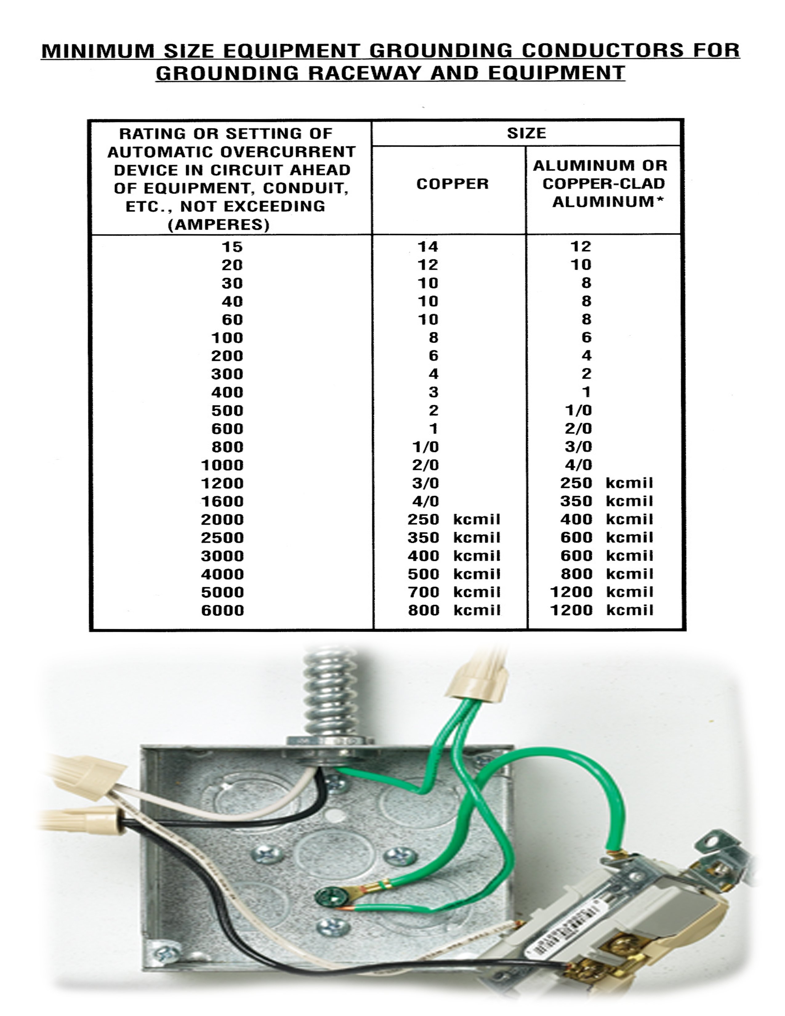
Equipment Grounding Chart (EGC)
The purpose of EGCs is to provide a low-impedance, ground- fault current path that reduces equipment to as close to zero potential as possible. NEC Table 250.122 relates the selection of size-appropriate EGC to the size of the over-current device ahead of the conductor. Section 250.122 (A) clearly states that aluminum and copper EGCs shall not be smaller than the values presented in this table, but also states that they are not required to be larger than the circuit conductors supplying the equipment.
As a rule-of-thumb (using calculations for verification), EGCs should not be less than 25 percent of the capacity of the phase conductors or the over-current device.